OmniCal Overview
OmniCal is a camera based calibration system which gives disguise the ability to “see”.
Overview
One of the big frustrations of our powerful 3D workflow has always been achieving accurate 3D models and calibrating those - solutions so far have been based around laser scanning or having a skilled CAD person on site who can modify the CAD model when inconsistencies are found between the 3D mesh and reality.
OmniCal removes the requirement to have accurate 3D models using its powerful calibration and Mesh Deform tools.
Workflow
Features
-
OmniCal uses structured light patterns to calibrate the relationship between projection surfaces, projectors and cameras.
-
The captured images are used to construct a 3D representation of projection surfaces as a point cloud.
-
Users then use the QuickAlign tool to manually align projection surfaces in the Disguise project to match their real world positions and proportions. This is an “offline” process which doesn’t require access to the physical stage.
-
We provide a single click Mesh Deform tool which deforms a 3D Model to match the real world (using the point cloud data)
-
Single click recalibration is supported if only projectors have moved. If cameras or projection surfaces have moved then an operator will need to adjust the previous alignment using current camera images.
-
The Disguise simulator also allows you to simulate cameras, view their coverage and perform test calibrations to ensure that the system will perform as required on site.
Warning: The simulator should be used as part of the production workflow to assess project suitability.
-
Supports 360° projection environments.
-
Designed for calibration of surfaces and scenes with 3D depth.
View the OmniCal Product page.
One camera option is available:
-
OmniCal MV system: For fixed installs. Reliable, continuous Ethernet camera connection; choice of lenses for three different fields-of-view; cameras only need setting up once.
Current limitations
-
The quality of the calibration will depend on having suitable lighting conditions.
-
Requires constant light levels during capture process.
-
Works best with low ambient light levels.
-
As mentioned above a Simulation must be run first to check project suitability. For large projects we recommend doing separate calibrations with groups of projectors and manually blending overlaps between the groups.
-
Requires non-reflective, opaque projection surfaces (no gauzes or mirrors).
-
Needs a few clearly defined feature points on the 3D mesh and real object, which can be visually identified on the camera images. Projection surfaces with sharp corners work well for example, but NOT smooth surfaces with no features.
-
OmniCal requires depth from the projectors point of view. Scene depth is particularly important when using moving elements such as Automation.
For a trained OmniCal operator
-
Create a simulated Camera Plan
-
Use the Disguise simulator to check project suitability.
-
You can place virtual cameras and simulate a capture and calibration. You will need to have a project file with projectors and projection surfaces in the same configurations and positions as they will be on-site.
-
The basic rule for camera placement is that at least 2 cameras need to see every point on your projection surface(s). Also cameras should also have a large angular separation. i.e the directions they face should not be parallel.
-
The simulation will help you determine how many cameras are needed, their positions and lenses and the calibration parameters. It will also show you the ideal calibration results you should expect on-site. Note that these ideal results are without real-world influences like unsuitable lighting conditions, reflections, occlusions, movement in the scene during capture etc.
-
Setup Cameras On-site
-
You will need to make sure the position, orientation and field-of-view of your real cameras matches your simulated Camera Plan. To help you with this, there is a camera setup editor that shows what the cameras are looking at.
-
When mounting the OmniCal MV system, you need to manually adjust the physical focus and aperture (iris) on the lens, so that the images of the scene are sharp and well exposed. Exposure time can be controlled from within Disguise.
-
From the Camera Setup tool you check how well Blob Detection is working (the dots that we project in the structured light patterns).
-
You may need to adjust camera parameters (like exposure time) according to the light level to get the best results.
Capture
Warning: A clear stage without movement or major lighting changes is required for this.
-
Capture is an automatic ‘one-button’ process that typically takes less than a minute. Exact duration depends on number of projectors, cameras and the resolution of the structured light pattern (number of blobs).
-
Once this is complete, the physical stage is free. The next steps can be done “offline”.
Calibration
-
You can view the point cloud after this stage and see check the calibration errors in pixels for each projector.
-
You may need to adjust calibration parameters to get the best results, but usually these will be chosen automatically.
Alignment
-
This is a manual step which aligns the point cloud with the projection surfaces in Disguise.
-
Users add alignment points to camera images to line up wireframe views of the projection surfaces with reality.
-
This only needs to be done once as long as cameras or projection surfaces do not move.
-
Re-shape points can also be added to correct the shape of the mesh. This can be thought of as a 3D warp from the camera’s point of view.
Mesh Deform
-
This is a final key step which deforms a mesh in Disguise software to match the real world by using the depth information from the point cloud.
For an untrained operator (recalibration)
-
Select Camera Plan
-
A user would select a Camera Plan previously created by a trained operator which contains known good settings for Capture, Calibration and Alignment.
-
Rig Check
-
This tool allows a user to compare live camera images to those from a previous Capture to check whether cameras or projection surfaces have moved. If so, the user can adjust the alignment reference points by dragging them into the correct positions.
-
Execute
-
A button which triggers a new Capture and Calibration using the settings from the Camera Plan.
-
No user interaction is required after this point. Projectors will automatically be calibrated at the end of this process.
Hardware
OmniCal Machine vision camera kit
The OmniCal MV system come in kits up to 4 or 8 (depending on kit size) and are perfect for fixed installs. They are powered via PoE, so only require a single Ethernet connection.
Lenses including 6, 8 and 12mm are incorporated into the kit depending on your project needs with a total of 24 lenses available, allowing for on the fly customisation to ensure the perfect setup.
Small Kit
Upper Foam
Up to 4 disguise MV Cameras
Lower Foam
Up to 12 Lenses
Options Include:
-
Fujinon 6mm Lens
-
Fujinon 8mm Lens
-
Fujinon 12mm Lens
Large Kit
Upper Foam
Up to 8 disguise MV Cameras
Lower Foam
Up to 24 Lenses
Options Include:
-
Fujinon 6mm Lens
-
Fujinon 8mm Lens
-
Fujinon 12mm Lens
Not included:
The kits do not contain network equipment like cables, switches or PoE injectors. The Disguise MV cameras require a switch that provides at least 1 GBit/s bandwidth and supports PoE to power the cameras.
Field of View options
The Disguise OmniCal kits offer camera and lens options to provide various needs in terms of camera coverage and Field of View angles (FOV).
The widest Field of View is with a disguise machine vision camera on a 6mm lens. The most narrow / tele option is with a 12mm lens.
Please note that the Field of View / opening angle depends on the focal length of the lens, and also the physical size of the image sensor. For example, the camera inside an iPod has a much smaller image sensor compared to the disguise MV cameras. Given a certain focal length, a smaller sensor will result in a smaller FOV than a larger sensor.
The focal length mentioned in a lens data sheet is usually the actual value, not the 35mm-film-equivalent. Therefore focal length values can only be directly compared for cameras with the same sensor size.
In our d3 software all information regarding focal length, 35mm-equivalents and FOV is either editable or automatically calculated, when editing a Camera in an OmniCal plan.
An overview of OmniCal camera and lens combinations and the resulting field of view:
Disguise G-507 machine vision cameras have a 3.908 crop factor (compared to 35mm film) when used with approved C-mount lenses.
| Focal length | Focal length 35mm equivalent |
Horizontal Field of View angle |
|---|---|---|
| 6 mm | 23.4mm | ~70.6 degrees |
| 8 mm | 31.3 mm | ~56 degrees |
| 12 mm | 46.9 mm | ~39 degrees |
| 25 mm | 97.7 mm | ~19.3 degrees |
Tips & tricks
-
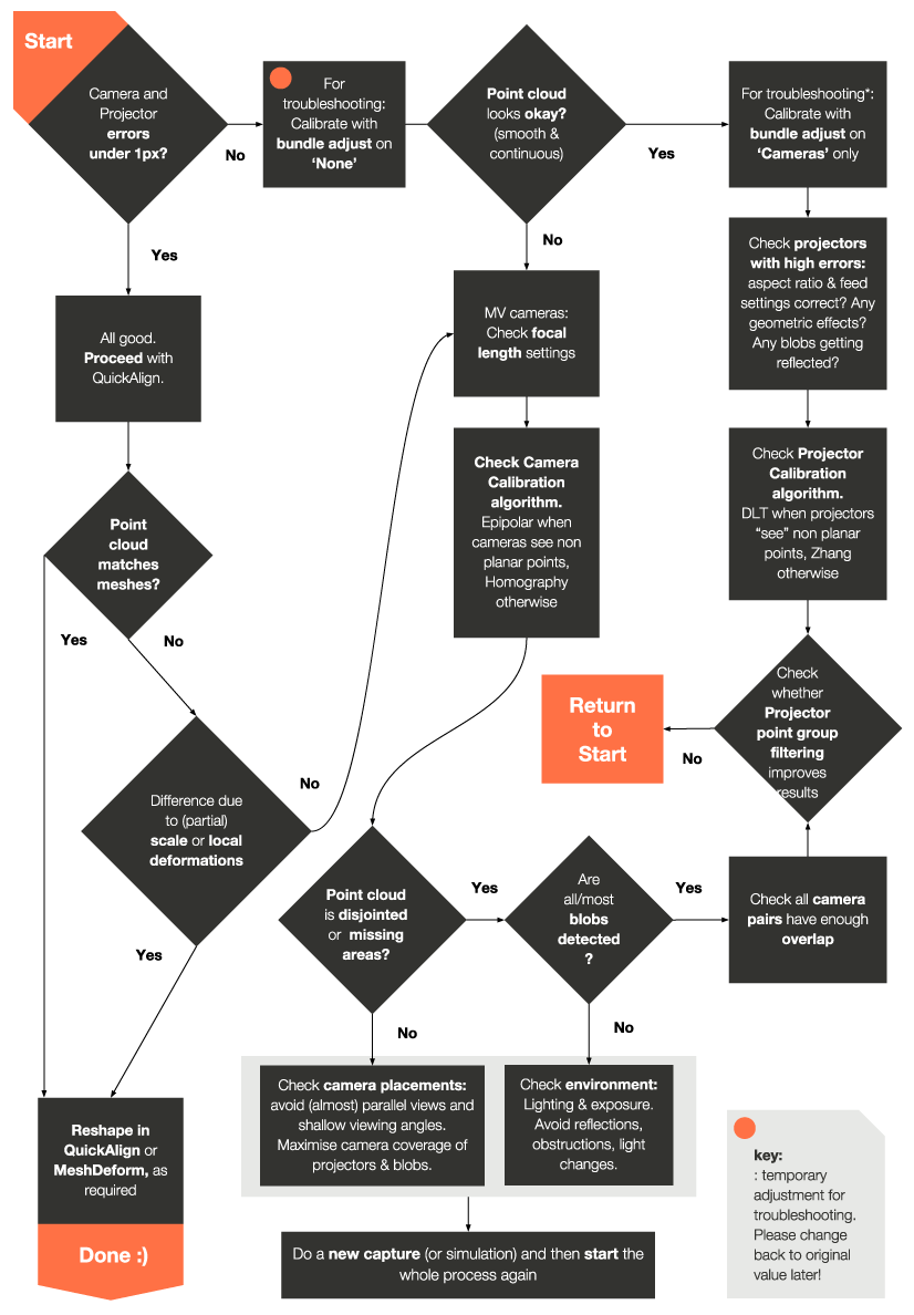
The fast way to tell if you have a good calibration is to look at the reprojection scores for each projector and camera in the calibration report (this is found at the very bottom) - any score below 1 pixel is considered good, similar to the error margin that would be accepted when using QuickCal.
-
Anything above 1 pixel usually indicates that something went wrong. In simulations you will normally see errors of around 0.5 pixels or below.
-
Avoid reflective surfaces as they can cause issues with calibration
-
Use surfaces with a lot of depth features as they make the calibration more accurate. It is especially important to have depth from each projector's "point of view". For example, if all the visible blobs from a projector land on a flat surface it will not be calibrated correctly. One way to fix this is to place an object in your environment temporarily during a capture to provide depth information.
-
Each blob needs to be seen by at least 2 cameras to be used in a calibration
-
Ensure blobs from across a projectors output can be seen. For example, if only blobs from the top left of a projector are detected it won't be calibrated correctly.
-
Ensure a large difference in angles of attack between cameras.
-
Capture Setup is important for good blob detection - you will most likely have to change the blob size, grid density and camera exposure to suit your environment.
-
Blobs should be as small as possible while still being detected by cameras. This improves the calibration accurancy. Also if they are too large they won't be detected at all.
-
Elongated blobs can cause higher calibration errors. Try reducing the blob size to handle this. Avoid large angles between the projector and projection surface normal e.g 45 degrees
-
More blobs doesn't mean a better calibration. Usually the default of grid size of 32 is sufficient. Use more blobs if you require a detailed point cloud for Mesh Deform.
-
Avoid lighting gradients, if the light level changes across an image blob detection may not work as well.
-
If you a calibrating a perfectly flat surface and getting strange results, toggle the epipolar/homography camera calibration algorithm under the Plan's Calibration Setup window and see if you get a better result.
-
If most blobs are landing on a flat surface this can skew the calibration results in favour of those areas. Enabling planar point removal in the Plan's Calibration Setup window may improve your results.
-
It can be difficult to line up geometrically symmetrical shapes (cubes / pyramids / bowl shapes). You could embed features or identification letters and numbers into the OBJ. You can also name reference points in the Quick Align window.
-
Surfaces without corners or visible reference points such as domes and cylinders are difficult to line up.
-
If you need to use mesh deform, use the point cloud visualisation mode to preview the results
-
Point cloud visualization affects performance, once you have verified the validity of your calibration, turn it off to ensure good performance.
Troubleshooting